- Nuclear Reactors, Boilers, Machinery And Mechanical Appliances; Parts Thereof
- Taps, Cocks, Valves And Similar Appliances For Pipes, Boiler Shells, Tanks, Vats Or The Like, Including Pressure-reducing Valves And Thermostatically Controlled Valves.
- Appliances For Pipes, Boiler Shells, Tanks, Vats Or The Like (excl. Pressure-reducing Valves, Valves For The Control Of Pneumatic Power Transmission, Check "non-return" Valves And Safety Or Relief Valves)
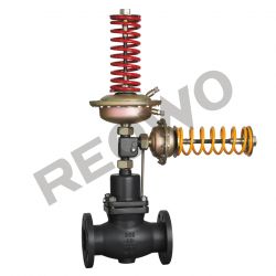
30D01D03Y、30D01D03R control valve
Product Images
Product Property
| Product Status : | New |
| Sample Available : | yes |
| Shipment Terms : | fob,cfr,cif,Negotiable |
| Payment Mode : |
T/T,L/C,WesternUnion |
Description
30D01D03Y/R self-operated pressure and differential pressure control valve

Summary
The30D01D03Y/30D01D03R self- operated pressure and differential pressure control valve is composed of the control valve, two actuators and two springs for pressure setting. It is suitable for controling differential pressure in the pipes of non-crrosive liquids, gases and steams .It works according to the priority action principle and two parameters can not be simultaneously controlled
The main features are as follows:
1.It has the pressure balancing function with high sensitivity.
2.Lownoise, reliable performance, free of maintenance
3.The standard modular design is adopted.
4 Various combined controls can be carried out through the assemblies.
Technical parameters and performances
Body
| DN | DN15、20、25、32、40、50、65、80、100、125、150、200、250mm | |
| PN | PN1.6、4 .0MPa | |
| Flange standard | ANSI、JIS、DIN GB JB(special standards can be offered according to user requirements) | |
| Body material | Cast iron (HT200), cast steel (ZG230-450), cast stainless steel (ZG1Cr18Ni9Ti, ZG1Cr18Ni12Mo2T i) | |
| Plug material | Hard seal | Stainless steel (1Cr18Ni9Ti, 1Cr18Ni12Mo2Ti) |
| Soft seal | Stainless steel embedded with rubber ring | |
| Pressure balancing | Stainless steel bellows (DN15~125), balanced diaphragm (DN150~250) |
Actuator
| Effective area (cm2) | 32 ※ | 80 | 250 | 630 |
| Pressure setting range | 0.8~1.6 | 0.1~0.6 | 0.015~0.15 | 0.005~0.035 |
| Minimum differential pressure that ensures normal work of the pressure valve | 0.3~1.2 ≥0.05 | 0.05~0.3 ≥0.04 | 0.01~0.07 ≥0.01 | ≥0.005 |
| Allowable maximum differential pressure between the upper a nd lower diaphragm chambers | 2 | 1.25 | 0.4 | 0.15 |
| Material | Diaphragm cover: galvanized steel sheet; | |||
| Diaphragm: EPDM or FKM with fiber | ||||
| Control pipeline connection | Copper pipe or steel pipe Φ10X 1(mm); | |||
| Ferrule connection: R1/4" |
Note: ※The pressure setting range correspond ing to the effective area does not apply to valves with Dn150
Performance
| Set value error | ±8% | ||
| Allowable leakage (under stipulated testing conditions) | Hard seal | 4×0.01% valve rated capacity | |
| Soft seal | DN15~50 | DN65-DN125 | DN150~250 |
| 10 bubbles/ min | 20 bubbles/min | 40 bubbles/min |

Allowable working temperature
| DN | 15~125mm | 150~250mm | |
| seal type | Hard seal | ≤150℃ | ≤140℃ |
| Cooling tank≤200℃ | Cooling tank and extension ≤200℃ | ||
| Cooling tan k and heat sink ≤350℃※ | Cooling tank and extension ≤300℃※ | ||
| Soft seal | ≤150℃ |
Note: ※It indicates the allowable working temperature is valid only when the medium is steam.
Rated flow coefficient, noise measuring coefficient, allowable differential pressure
| DN | 15 | 20 | 25 | 32 | 40 | 50 | 65 | 80 | 100 | 125 | 150 | 200 | 250 |
| Rated flow coefficient | 4 | 6.3 | 8 | 16 | 20 | 32 | 50 | 80 | 125 | 160 | 280 | 320 | 450 |
| Noise measuring coefficient Z value | 0.6 | 0.6 | 0.6 | 0.55 | 0.55 | 0.5 | 0.5 | 0.45 | 0.4 | 0.35 | 0.3 | 0.2 | 0.2 |
| Allowable differential | PN16 | 1.6 | 1.5 | 1.2 | 1 | ||||||||
| pressure (Mpa) | PN40 | 2 |
Working principle
According to different combinations, refer to the working principle of the self-operated (before/after-valve) pressure control valve and self-operated differential pressure control valve (valve closed/opened when pressure rises). (working according to the priority action principle)

I. Dimensions and weight of control valve
| DN (mm) | 15 | 20 | 25 | 32 | 40 | 50 | 65 | 80 | 100 | 125 | 150 |
| L (mm) | 130 | 150 | 160 | 180 | 200 | 230 | 290 | 310 | 350 | 400 | 480 |
| B (mm) | 212 | 212 | 238 | 238 | 240 | 240 | 275 | 275 | 380 | 380 | 326 |
| B1(mm) | — | — | — | — | — | — | — | — | — | — | 630 |
| Weight(Kg) | — | — | — | — | — | — | — | — | — | — | 140 |

II. Dimensions and weight of actuator
| Effective area (cm ) | 32 | 80 | 250 | 630 |
| R (mm) | 172 | 172 | 263 | 380 |
| H (mm) | 435 | 430 | 470 | 520 |
| Weight(Kg) | 7.5 | 7.5 | 13 | 28 |

