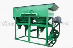
xinhai Jig
Product Images
Product Property
| Product Status : | New |
| Sample Available : | yes |
| Shipment Terms : | fob,cif |
| Payment Mode : |
T/T |
Description
Introduction
Jig concentrators are devices mainly used in the mining industry for mineral processing, to separate particles within the ore body, based on their specific gravity (relative density). The particles should be in similar size. And Jig is mainly used to handle placer gold, tungsten, tin, hematite and beach placer.
Features
1. Sawtooth wave jig is revised and manufactured, based on the stratified theory and the adequate analysis of other conventional jigs. The jigging pulsation curve----produced by sawtooth wave jig----is in the shape of sawtooth wave which makes upward water flow quicker than downward water flow.
2. The feature that upward time is shorter than downward time solves the problem that time and action of upward/downward water flows. This breakthrough dramatically amplifies the loose degree and mitigates suction action, which facilitates precipitation of coarse ores and improves ore recovery rate.
Application
Jig is mainly used to handle placer gold, tungsten, tin, hematite and beach placer.
Working principle
The particles are introduced to the jig bed (usually a screen) where they are thrust upward by a pulsing water column or body, resulting in the particles being suspended within the water. As the pulse dissipates, the water level returns to its lower starting position and the particles once again settle on the jig bed. As the particles are exposed to gravitational energy whilst in suspension within the water, those with a higher specific gravity (density) settle faster than those with a lower count, resulting in a concentration of material with higher density at the bottom, on the jig bed. The particles are now concentrated according to density and can be extracted from the jig bed separately.
Technical parameters
| Type | Model | Length×width | Jigging chamber area | The number of general jigging chamber | General area of jigging chamber (m2) | Stroke coefficient |
| Lateral driven | LTP-34/2 | 450×300 | 0.135 | 2 | 0.27 | 0.58 |
| Bottom driven | LTA-55/2 | 500×500 | 0.25 | 0.5 | 0.5 | |
| LTA-1010/2 | 1000×1000 | 1 | 2 | |||
| Re-vibrating | ||||||
| Side driven | LTC-69/2 | 900×600 | 0.54 | 1.08 | 0.56 | |
| 2LTC-79/4 | 900×700 | 0.63 | 4 | 2.52 | 0.48 | |
| 2LTC-912/4 | 1200×900 | 1.08 | 4.32 | 0.49 | ||
| 2LTC-366/8T | 600×(300~600) | 0.2~0.34 | 8 | 2.16 | 0.68~0.40 | |
| 2LTC-6109/8T | 900×(600~1000) | 0.58~0.86 | 5.76 | 0.52~0.35 |
| Type | Model | Diaphragm stroke | Diaphragm | The maximum Feed size | Processing capacity | Water consumption | Motor power | Weight |
| Lateral driven | LTP-34/2 | 0~25 | 320; 420 | 12 | 2~6 | 4~10 | 1.1 | 750 |
| Bottom driven | LTA-55/2 | 0~26 | 250;300;350 | 5 | 1~5 | 4~20 | 1047 | |
| LTA-1010/2 | 0~25 | 250;300;350 | 5~15 | 20~60 | 22 | 1516 | ||
| Re-vibrating | 0~5 | 400~750 | 2~10 | 4~5 | 40~45 | 1.7 | 1620 | |
| Side driven | LTC-69/2 | 0~50 | 220~350 | 12 | 6~9 | 40~60 | 15 | 1420 |
| 2LTC-79/4 | 160~250 | 5~15 | 20~90 | 22 | 2450 | |||
| 2LTC-912/4 | 160-250 | 7~25 | 60~120 | 3 | 3500 | |||
| 2LTC-366/8T | 120~300 | 5 | 3~6 | 20~40 | 1.1×2 | 1600 | ||
| 2LTC-6109/8T | 10~20 | 80~120 | 2.2×2 | 4650 |


